
A thermal interface material rarely fails in a way you can see from outside the pack. The cells still sit on the cooling plate, the bolts are still tight, and nothing has visibly moved. What changes is the thermal resistance of the joint: a little air gets in, a layer goes stiff, a bond lets go along one edge. The cells above that patch then run warmer than their neighbours, age faster, and drag the pack’s usable capacity down with them. This page groups the ways a TIM loses its thermal (and sometimes electrical) function, what drives each one, and which material families are most exposed.
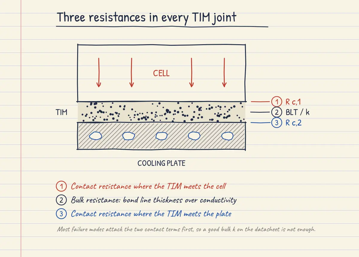
It helps to keep the resistance stack in mind. Heat crossing the joint sees a contact resistance at the cell side, the bulk resistance of the layer itself, and a second contact resistance at the plate:
where BLT is the bond line thickness and kTIM the bulk conductivity. Every mechanism below works on one or more of those three terms. Most of them attack the two contact terms first, which is why a material can look fine in a bulk conductivity test and still perform badly in the pack.
Mechanical and flow-driven failures
Pump-out
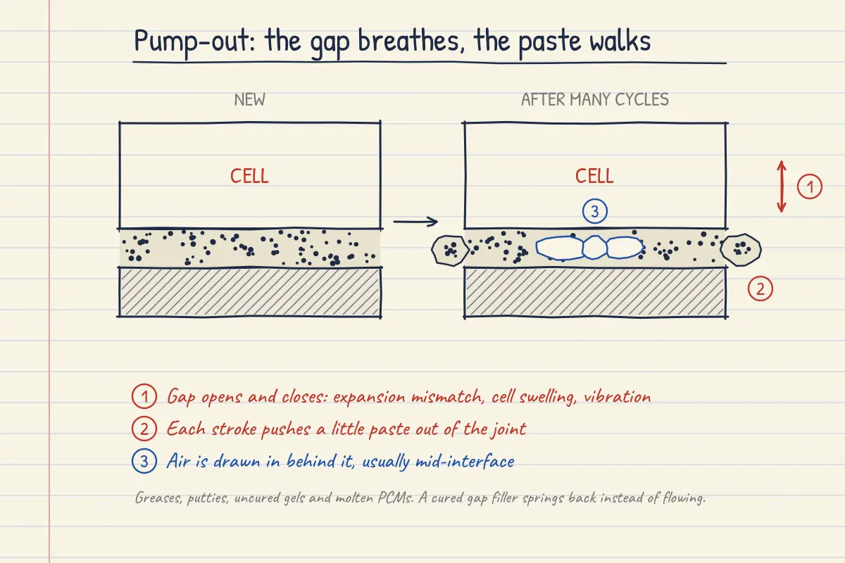
Non-curing materials (greases, putties, uncured gels, and phase change materials while molten) behave as yield-stress fluids rather than solids. When the gap they sit in opens and closes repeatedly, a little material is pushed out of the joint on each stroke and does not all come back. In electronics the stroke comes from warpage of the die or substrate as it heats and cools; in a battery it comes from differential expansion between cell and plate, from cells breathing as they charge and discharge, and from vibration. The lost volume is replaced by air, so the damage concentrates where the movement is largest, usually the centre of a large interface. Work at Fraunhofer on accelerated pump-out testing found two mechanisms acting at once: transport of the fluid phase (which can actually be a pump-in) and air being drawn into the joint1. Fully cured gap fillers largely avoid this because, once crosslinked, they recover elastically rather than flowing; supplier datasheets make the point that a cured filler keeps enough modulus to resist pump-out while staying soft enough to absorb expansion stress2.
Delamination
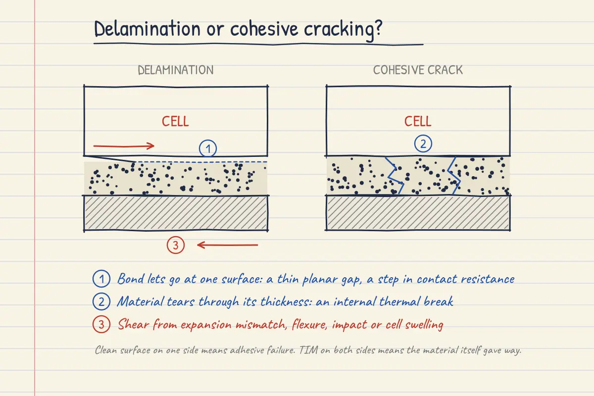
Cured gap fillers and thermally conductive adhesives fail differently: they stay in place, but the bond to one surface lets go. Shear from expansion mismatch, a crash or kerb strike, pack flexure, or cell swelling pulls on the interface, and if adhesion is weaker than the bulk material the crack runs along the surface. Poor surface preparation, mould release on the cell wrap, oxidised or oily aluminium, and low-energy plastic coatings all make this more likely. The result is a planar gap, often only microns thick, that shows up as a step in contact resistance rather than a change in the bulk. CALCE temperature-cycling work on filled-polymer TIMs found most materials changed little, but scanning acoustic microscopy picked up delamination in one group of gap pads3. Parker’s reworkability study is a useful reminder that whether a filler fails adhesively or cohesively depends on the substrate surface as much as on the material4.
Cohesive cracking
The opposite case: adhesion holds and the material itself tears. Reaching 3 W/m·K and above typically means loading a polymer with a large volume fraction of ceramic filler, and every increment of filler reduces the elongation the matrix can tolerate. Stiffer chemistries (epoxies, some polyurethanes) and materials cycled through their glass transition are most at risk. The same CALCE study saw cracking in putty samples after cycling, and one putty degraded as its bulk properties shifted near the glass transition3. A crack running through the layer acts as a thermal break even though both surfaces are still wetted.
Compression set and stress relaxation
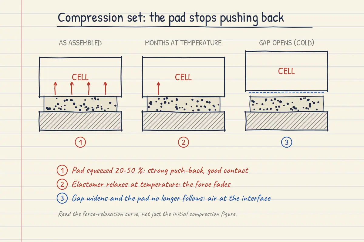
Pre-cured gap pads rely on being squeezed. Held under load at temperature, the elastomer relaxes: the force it pushes back with falls, and if the gap later widens (cold soak, cell contraction at low state of charge) the pad does not spring back to follow it. Contact pressure drops and contact resistance rises. Some soft pads are designed to relax quickly on purpose to protect fragile components; Parker quotes close to a 90% drop in compression force within an hour for one high-conductivity pad5. That is good for the cell can and bad if the design depended on a sustained clamping force. Read the force-relaxation curve, not just the initial compression figure.
Degradation of the material itself
Oil bleed and dry-out
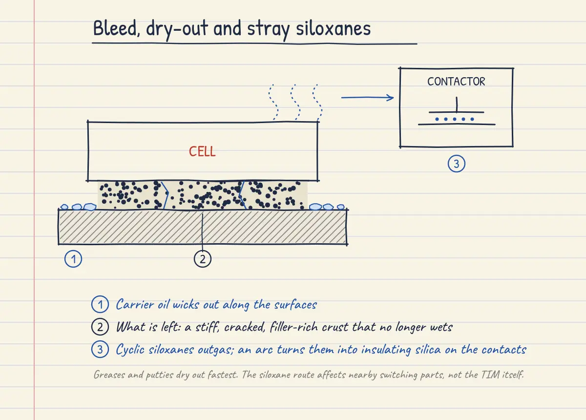
Most TIMs are a carrier fluid holding a packed bed of filler. With time and temperature the carrier can leave: it wicks out along surface roughness, or the lighter fractions evaporate. What remains is a filler-rich crust that no longer wets the surfaces or follows their movement, so contact resistance climbs and the layer becomes brittle. NREL and DuPont tracked exactly this, alongside pump-out, in commercial greases cycled between -40 and 125 °C6, and Electronics Cooling’s review of grease reliability names pump-out and dry-out as the two main causes of rising grease resistance7. Greases and non-reactive putties are most exposed; low-crosslink gels and soft pads can bleed oil too.
Volatile siloxanes and contact contamination
Silicone TIMs contain a small fraction of low molecular weight cyclic siloxanes (D4 and its neighbours). These volatilise slowly, travel through the pack air, and can deposit on switching contacts. When an arc decomposes them they leave silica, an insulator, on the contact face8. Relay makers are blunt about it: Omron advises against silicone coatings near relays at all, noting that even reduced-siloxane grades only delay the problem9. For a battery this is a system concern rather than a TIM thermal failure. The TIM still conducts heat, but it can shorten the life of contactors, pre-charge relays and connectors sharing the enclosure. Low-volatile and non-silicone grades exist for this reason.
Cure inhibition
Two-part addition-cure silicones use a platinum catalyst, and that catalyst is easily poisoned. Dow lists nitrogen compounds (amines, amides), sulfur compounds, tin salts from condensation-cure silicones, phosphorus and a handful of other elements as inhibitors10. In a pack the likely sources are sulfur-cured rubber seals, amine-cured epoxy or polyurethane on adjacent parts, residues from tin-cured sealants, and some primers and coatings. The affected region stays tacky or liquid, and an uncured patch then behaves like a grease: it can pump out, bleed and fail to hold the cell. Inhibition is often local, at the interface with the contaminated surface, so it can hide under a layer that looks cured from the edge.
Thermal and hydrolytic ageing
Every polymer matrix has a ceiling. Polyurethane gap fillers are generally rated lower than silicones, and the existing Options for Thermal Interface Materials post puts the usual urethane limit below about 130 °C. Silicones tolerate much higher temperatures in open air, but in a sealed, warm, slightly damp space some addition-cure silicones can revert, softening back towards a gum. Specifications exist for reversion-resistant silicone potting compounds precisely because of this11, and at least one urethane gap filler is marketed on the basis that it will not depolymerise when heated in confined spaces12. Battery packs are sealed enclosures, so the confined-space test conditions are the relevant ones, not the open-air temperature rating on the datasheet.
Electrical and interfacial failures
Loss of electrical isolation
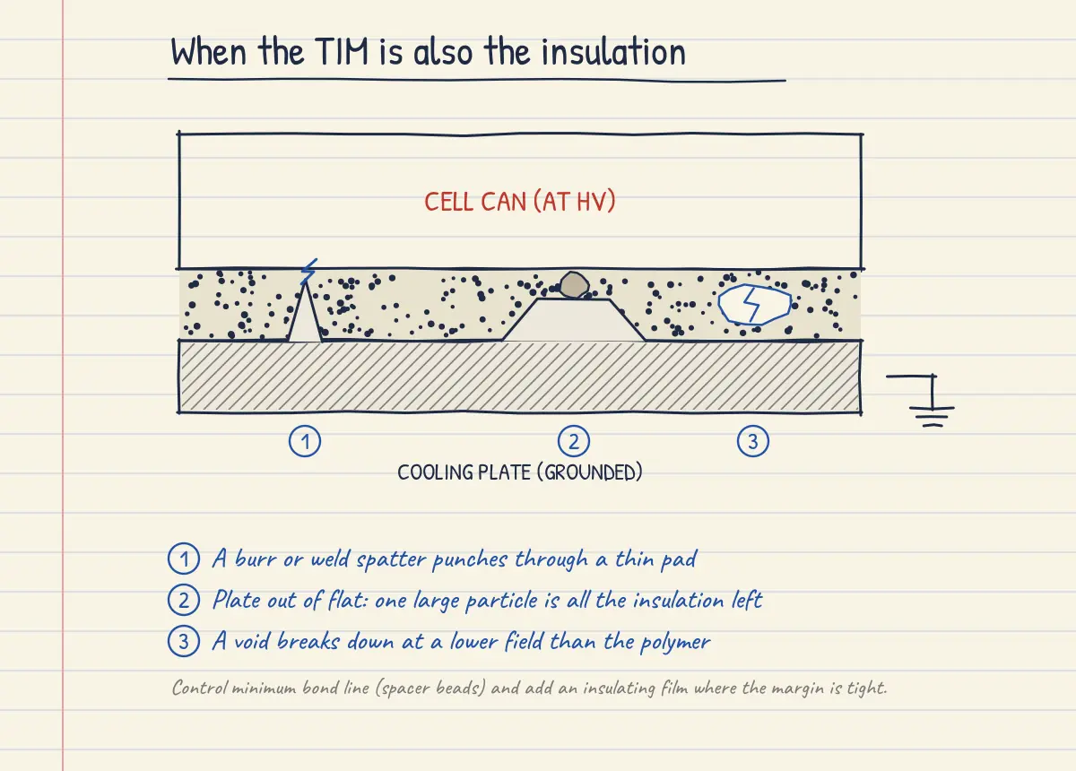
In many packs the gap filler is the only electrical barrier between a live cell can (or a busbar plate) and a grounded cooling plate, and gap filler suppliers list dielectric strength as one of the properties they balance against conductivity13. Isolation can be lost in several ways: the bond line is thinner than designed somewhere, so the remaining insulation is a few large filler particles; a burr on the plate or a weld spatter on the can punches through a thin pad; or voids leave an air gap that breaks down at a lower field than the polymer. Any of these turns a thermal defect into an isolation fault, which the BMS will (or should) flag. Controlling minimum bond line, often with spacer beads in the filler, and adding a dedicated insulating film where margins are tight are the usual defences.
Corrosion at the interface
Moisture that reaches the bond line, together with ionic residues from cure catalysts, cleaning or the filler itself, can attack bare aluminium plates and copper. The oxide or hydroxide that grows sits exactly where it does most harm, between the TIM and the metal, so it raises contact resistance and undermines adhesion at the same time. This one is more often suspected than proven in packs, so treat it as a check item in humidity testing rather than a known dominant mode.
Process-induced failures
Many TIM problems are built in on the day the pack is assembled.
- Trapped air. A dispense pattern that closes on itself (a ring, a crossed pattern with sealed corners) traps air when the cells come down. The TIM Application Pattern post shows the patterns used to avoid this.
- Short bond line or short shot. Too little material, or a plate that is out of flat, leaves areas with partial contact.
- Off-ratio mixing. Two-part materials cured at the wrong ratio stay soft or cure brittle. Highly filled pastes are abrasive, and wear in pumps and metering valves can drift the ratio over a production run; some suppliers formulate with softer fillers specifically to reduce abrasion14.
- Settled material. Dense fillers can settle in drums and cartridges. One supplier recommends putting cartridges in a homogeniser for several minutes before dispensing15. If the top of a drum goes on first and the bottom last, the filler content (and therefore conductivity and cure) varies through the build.
- Expired material. Two-part fillers often carry shelf lives of six months or less, and suppliers will not recertify expired lots2.
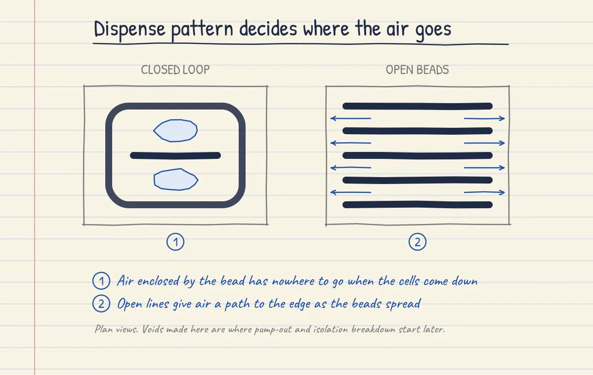
Process defects also feed the in-service modes above: a void is where pump-out and isolation breakdown start, and an off-ratio patch is where bleed and cracking start. See Pack Defects for how these are detected on the line.
Filler migration
A quieter mode is the filler moving relative to the matrix without the material leaving the joint. Squeeze flow during assembly can drive liquid out ahead of the particles, leaving a jammed, filler-rich centre and resin-rich edges, and particles can drift away from walls under shear. The layer is still there, but the conductivity is no longer uniform. This is covered in more detail in Filler Migration in TIMs.
Summary
| Failure mode | Main driver | Most exposed | What it does to the joint |
|---|---|---|---|
| Pump-out | Cyclic gap change (thermal, swelling, vibration) | Greases, putties, uncured gels, molten PCMs | Air replaces material, mostly mid-interface |
| Delamination | Shear, flexure, poor surface prep | Cured gap fillers, adhesives, firm pads | Thin planar gap, contact resistance step |
| Cohesive cracking | Strain beyond elongation limit, Tg cycling | Highly filled epoxies, PUs, putties | Internal thermal break |
| Compression set | Sustained load at temperature | Pre-cured pads | Loss of contact pressure when gap opens |
| Bleed and dry-out | Time at temperature | Greases, putties, soft gels and pads | Stiff crust, loss of wetting |
| Siloxane outgassing | Temperature, sealed volume | Silicones | Contact failures in nearby relays and contactors |
| Cure inhibition | Contamination (S, N, Sn, P) | Pt-cured silicones | Uncured, tacky regions |
| Thermal or hydrolytic ageing | Heat in a sealed, damp space | PUs at high temperature; some silicones | Softening or embrittlement |
| Loss of isolation | Thin spots, burrs, voids | Thin pads, uncontrolled bond lines | Isolation fault |
| Process defects | Dispense, mixing, storage | Dispensed fillers | Voids, variable conductivity, partial cure |
Testing for them
Bulk conductivity on a fresh sample tells you little about any of the above. The tests that do are run on a sandwich of the real substrates at the real bond line: thermal resistance by an ASTM D5470-type method before and after temperature cycling, damp heat and vibration, with scanning acoustic microscopy to find voids and delamination. Dow has described running D5470 measurements on gap fillers in bond-line geometry through heat/humidity cycling and isothermal ageing16, and Nissan published a specimen-level method for gap filler interfacial resistance aimed at predicting durability17. Add a cure check against every material the filler touches, a pull-off test to see whether failure is adhesive or cohesive, and an isolation test after the environmental sequence.
References
- Accelerated Pump Out Testing for Thermal Greases, EuroSimE 2019, Fraunhofer (doi:10.1109/EuroSimE.2019.8724540)
- Thermal Interface Selection Guide, Gap Filler 3500S35, Bergquist (Henkel)
- Effects of Temperature Cycling and Elevated Temperature/Humidity on the Thermal Performance of Thermal Interface Materials, IEEE Trans. Device and Materials Reliability 9(3), 2009, CALCE
- The Right Amount of Stress: Reworkability of Gap Fillers in EV Battery Packs, Parker LORD white paper
- High-Performance Thermal Gap Pad Offers Very Low Oil Bleed, Parker Chomerics, November 2024
- D. DeVoto et al., Degradation Characterization of Thermal Interface Greases, NREL / ITherm preprint
- Reliability Testing of Thermal Greases, Electronics Cooling, November 2007
- Siloxane Monitoring for Contact Failure of Electrical Parts, HORIBA
- Relay FAQ: silicone and urethane coatings near relays, Omron
- FAQ: Platinum Catalyzed Silicone Inhibitors, Dow
- SAE AS81550B, Insulating Compound, Electrical, Embedding, Reversion Resistant Silicone
- CoolTherm UR-3000 Technical Data Sheet, Parker LORD
- Silicones for battery thermal management, conference slides, 2023
- CoolTherm SC-2000 RW Technical Data Sheet, Parker LORD
- PK404DM Two-Part Thermal Conductive Gap Filler datasheet, LiPOLY
- A. Becerra, EV Gap Filler Thermal Conductivity Measurements upon Aging in Bondline Geometry, Dow (NETZSCH seminar abstract)
- R. Naganuma, T. Nagashima, E. Ishizuka (Nissan), Established the Evaluation Method on the Thermal Resistance of Gap Filler for EV Battery Pack, JSAE Transactions 53(2), 2022
See also: Thermal Interface Materials, Options for Thermal Interface Materials, Thermally Conductive Adhesives, TIM Application Pattern, Phase Change Material, Cooling Plate Design, Pack Defects, Adhesives