
Fraunhofer ISE has run a 25 Ah pouch cell with a silicon-rich anode through more than 1,000 full cycles and kept over 83% of its capacity [2]. The same lab ran the cell at two clamping pressures, and the result depends heavily on which one. Pressure is the lever a pack designer controls, so this post covers the material, what Fraunhofer reported and what it implies for compression hardware and the BMS. It is a companion to Options that Solve the Expansion of Silicon Anodes.
How the material is made
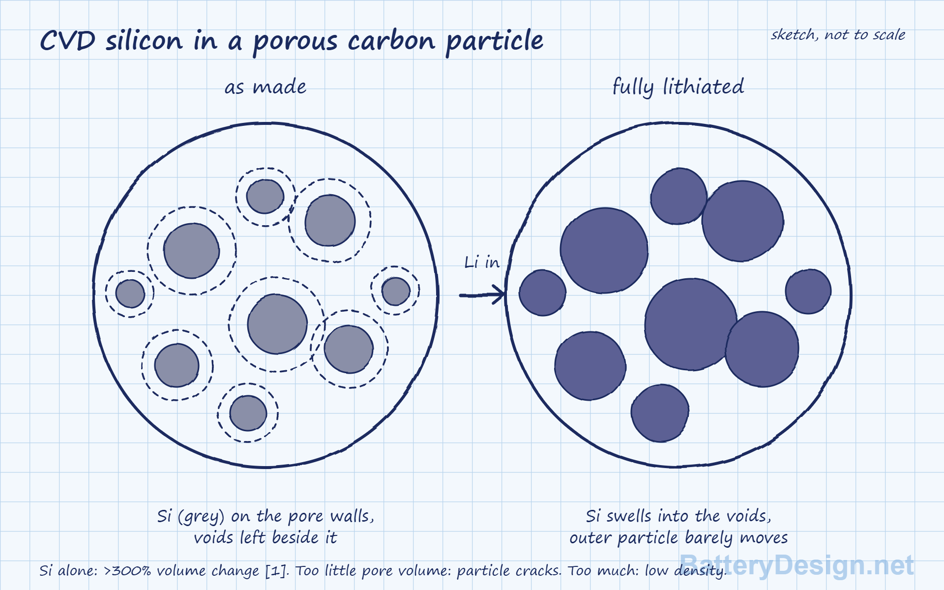
In a CVD silicon-carbon composite, a silicon-bearing gas, normally silane, passes over a porous carbon powder and decomposes inside the pores, leaving nanoscale silicon on the pore walls. An outer carbon coat usually follows [1]. The outcome depends on how the gas enters, adsorbs, decomposes and nucleates, so this is not simple pore filling [1].
The reason for the design is mechanical. Silicon can expand by more than 300% when fully lithiated [1], which cracks ordinary silicon particles and keeps breaking the SEI (see Challenges of Adding Silicon to Graphite Anodes). Here the silicon sits in voids, and the empty pore volume takes up much of the swelling. Pore volume is therefore the key design variable. Too little and the silicon has nowhere to grow. Too much and the particle loses density, and overfilling can block transport channels [1].
What Fraunhofer built and tested
The StrOboBatt project built 40-layer, 25 Ah pouch cells from commercially available electrode foils, with a silicon-carbon and graphite anode and a nickel-rich NMC cathode [2]. The silicon-carbon composite is 51% of the anode active material. The anode delivers over 1,000 mAh/g and over 5 mAh/cm² [2]. The release calls the material a silicon-carbon composite and does not say how it was made, so the CVD route above is background, not a statement about these cells.
| Item | Value | Status |
|---|---|---|
| Energy density, research format | 280 Wh/kg | Measured [2] |
| Energy density, industrial pouch format | About 330 Wh/kg | Expectation [2] |
| Cycle life | Over 1,000 full cycles, over 83% retained | Measured at 1,000 kPa [2] |
| Test conditions | 1C (one hour) charge and discharge, 300 and 1,000 kPa axial pressure, check-up cycles at lower rates | Reported [2] |
Fraunhofer’s team treats more than 1,000 cycles at 80% or better as the industry target for silicon-rich anodes [2]. Our arithmetic on the energy figures: 330 against 280 Wh/kg is 18% more, so the research pouch format gives away roughly that much to packaging that an industrial format would recover. The 330 is an expectation, not a measurement.
What Fraunhofer says about pressure
At 1,000 kPa the cells kept over 83% after more than 1,000 full cycles. At 300 kPa the usable capacity fell significantly faster, particularly at 1C [2]. Marc Kissling, group leader at Fraunhofer ISE, calls cell pressure “an important parameter for the stable operation of silicon-rich pouch cells” [2]. The release’s explanation is that axial pressure improves interfacial resistance and reduces the risk of electrode materials detaching from each other and from the foil [2].
The two test pressures map onto numbers we already use. 300 kPa is 3 bar, the top of the 0.5 to 3 bar range typical of production modules on our stack pressure page. 1,000 kPa is 10 bar. On a graphite and NMC811 pouch cell, the Wang et al. study covered on that page put the best cycle life at 12.5 bar (over 375 cycles to 80%) against 169 cycles at 3 bar. Different cells and different tests, so this does not show that silicon needs more pressure. It does show two groups seeing the better result near 10 bar and the weaker one at a production-typical 3 bar.
The second finding concerns the BMS. The gap between residual capacity at a low discharge rate and the capacity available in regular 1C operation grew over the test [2]. Fraunhofer concludes that silicon-rich cells need evaluating under real operating conditions, not on capacity retention alone. Our reading: a slow check-up capacity will overstate what the pack can deliver at working power, so derate the power and energy map with age. Validation profiles should state the rate and the clamping pressure.
What it means for pack design
Our arithmetic on an illustrative 200 mm by 100 mm cell face: 1,000 kPa is about 20 kN of clamping force, roughly 2 tonnes-force, and 300 kPa is about 6 kN. Treat 1,000 kPa as the design target for high-silicon pouch cells until other data says otherwise, and make the compression system stiff and creep-resistant enough to hold it as the cells swell over life.
Module numbers show how the load builds. On the 148 mm by 91 mm face of the PHEV2 prismatic cells in our stack pressure example, a 12-cell NMC/graphite module starts at about 3 kN on the end plates (2.23 bar) and reaches about 30 kN (22.3 bar) at end of life. Reports reaching us put NMC/graphite plus silicon modules at about 50 kN. On the same face area that would be about 37 bar, our arithmetic from an unconfirmed figure.
Nigel: A typical 12-cell prismatic NMC/graphite module starts near 3 kN and reaches about 30 kN at end of life. From what I have heard, NMC/graphite plus silicon can reach about 50 kN. It would be good to find more data on this.
Cell-level data agree on the direction. In a University of Stuttgart study of NMC811 pouch cells held at 200 kPa, thickness from the end of formation to full charge grew from 4.37 to 4.44 mm for graphite, from 3.61 to 3.82 mm for a 34 wt% Si-C and graphite anode, and from 3.62 to 3.93 mm for 34 wt% SiOx and graphite [3]. That is about 1.6%, 5.8% and 8.6% (our arithmetic), so silicon multiplies the reversible stroke the pack must absorb by roughly 3.5 to 5.5 times in that study. The paper reports thickness, not force. For the soft, foam-buffered side of the problem, see The Form Factor Dilemma in High-Silicon Anodes.
Read it with care
This is one lab, one cell design and a research format. The temperature, the retention figure at 300 kPa, the cell dimensions and any pack-level data are not published, and the 330 Wh/kg figure is an expectation. The result shows that pressure matters for a silicon-rich cell. It does not give a pressure specification.
References
- Li, A., Hua, S., Tang, Y., Sun, L., Shao, Q., Zhu, D. and Bai, R., Rational Design of Porous Carbon Hosts for Silicon/Carbon Anodes in Lithium-Ion Batteries, Molecules 31(14), 2483 (2026). Review.
- Fraunhofer ISE, Fraunhofer ISE Successfully Tests High-Energy Battery Cells with Silicon-Rich Anodes Over 1,000 Cycles, press release, 20 October 2026 (StrOboBatt project)
- von Kessel, O., Avdyli, A., Vrankovic, D. and Birke, K.P., Swelling, pressure evolution and aging in high-silicon/graphite composite lithium-ion batteries, Journal of Power Sources 610, 234582 (2024)
See also: Silicon Anode, Options that Solve the Expansion of Silicon Anodes, Cell Electrode Pressure and Expansion, Cell Electrode Pressure, Current Collector
Get the next teardown in your inbox
New teardowns, benchmarks and design data from BatteryDesign.net, free by email. Unsubscribe any time.