
A humanoid robot asks for something an electric car never does: a battery that fits inside a torso, delivers short, sharp bursts of power to dozens of joint motors and the onboard compute at the same time, and still lasts a working shift. This post lays out those requirements and why they push the industry towards small cylindrical cells.
The requirements
Runtime is the headline gap. LG Energy Solution says most humanoids today manage only about two to four hours on a charge, against the eight to twelve hours of an industrial shift.[1] Closing that gap with a fixed-volume torso pack means maximising cell-level energy and minimising dead space, which is the same logic as the volumetric argument in Cell Energy Density Roadmap to 2035.
Power is the opposite pressure. Walking, balancing and lifting load many actuators at once, so the peak-to-average ratio is high and the transients are fast. A pack that is energy-optimised but cannot hold its voltage under those pulses will brown out the controllers. The design therefore sits between an energy cell and a power cell, and the cell choice is a trade between them. The effect of high C-rate on the cell is discussed in Megawatt Charging: What 1,000 kW and 10C Mean for Cell and Pack Design.
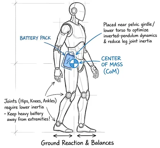
Safety is the third. A robot works near people, often indoors, with the pack a few centimetres from its own chassis. LG describes safety as the most critical factor and points to stable operation, precise thermal management, early abnormality detection and pack-level thermal propagation prevention.[1] The mechanics of propagation in a small pack are covered under Propagation Mitigation.
Why cylindrical cells
Cylindrical cells suit this job for reasons that are mostly mechanical. The steel can is rigid and its geometry is well understood, cells can be arranged to fit awkward volumes, and the supply base for high-power small-format cells is mature. LG’s robot-oriented examples are 2170 NCMA cells in three flavours: the M58 for capacity, the H51 for a balance of energy, power and weight, and the H52A for very high power, with an 8C maximum discharge and charging in about 15 minutes.[1] The company says ternary and quaternary chemistries are favoured over LFP here because energy density matters more than cost per kWh.[1] For the format itself see 21700 Cylindrical Cells and Tabbed vs Tabless Cylindrical Cells.
For Boston Dynamics’ Atlas, industry sources reported in February 2026 that LG supplies a 46-series cylindrical ternary cell, with the selection said to follow the robot’s CES 2026 showing.[2] The two LG-related sources use different format names (2170 in LG’s own robotics article, 46-series in the Atlas report), which probably reflects different products in different applications, so treat the cell for any particular robot as unconfirmed unless the manufacturer states it. No capacity, voltage or pack figures were published in either source.
Where solid-state fits
LG notes that solid electrolytes remove leakage risk after impact and offer high thermal stability, which is attractive for a robot that may fall.[1] Its cited SNE Research projection puts robot-specific solid-state capacity at only 0.04 GWh in 2030, against 1.37 GWh for all humanoid battery demand that year,[1] so near-term packs will still be liquid-electrolyte lithium-ion. The timeline context is in Solid-State Production Timelines.
A requirements cascade
One useful way to frame the design is to cascade from the task down to the cell. Shift length and duty cycle set the pack energy; the number of simultaneously loaded joints sets peak power; the torso volume and mass budget set the allowable cell count and format; the proximity to people sets the propagation and venting strategy. Each step constrains the next, and a change in the robot’s task (a heavier payload, say) moves the cell choice. Related application pages, such as Industrial Robots, show how other duty profiles shape the cell.
The table below puts that into six steps. Each row takes the output of the one above as its input. The ranges are deliberately missing: we could not find a published, independently sourced peak power or pack-level density target for a production humanoid, so the table gives the direction of each constraint and the numbers come from the examples that follow.
| Step | Driver | What it sets in the pack | What lands on the cell |
|---|---|---|---|
| 1. Mission and shift | Shift length, charging strategy (opportunity charge or swap) | Usable energy and daily energy throughput | Capacity, cycle life and charge rate |
| 2. Motion and payload | Joints loaded at once, payload, recovery from a stumble | Steady load against pulse load, and energy returned on the way down | Pulse power, DCIR and charge-pulse acceptance |
| 3. Distribution | Harness routing through hip and shoulder, motor drive voltage | Bus voltage, series count and connector current | The layout of cells (Ns by Np), much less the stress on each one |
| 4. Torso envelope | Cavity shape, centre of mass, mass budget | Volume and mass available to the pack | Cell format, Wh/kg and Wh/L |
| 5. Thermal boundary | Sealed torso, heat path shared with compute and drives | How heat leaves the pack | Tab layout, path from cell to cooling surface, rate limits |
| 6. People nearby | Indoor use, falls, no fence | Propagation barriers, vent direction, shock retention | Chemistry, separator and can or pouch choice |
Worked example: does a higher bus voltage change the cell’s workload?
A common assumption is that moving a robot from a 14S to a 28S pack, to keep harness current down, forces the cells to work harder because each parallel group gets smaller. We checked this with a simple case. The relationship that matters is the per-cell current for a given pack power, where P is pack power, Ns and Np are the series and parallel counts and Vcell is the nominal cell voltage:
Take 56 cells of 5 Ah at 3.6 V nominal, which is the same cell count as the Spot Explorer pack in our Boston Dynamics Spot Battery analysis, and a 3 kW peak demand. The 15 mΩ cell DCIR is an illustrative figure that Nigel considers reasonable for a cell of this type, not a measured value for a specific cell. See DCIR of a Cell for how to get a real one.
| Layout | Nominal voltage (V) | Energy (kWh) | Pack current at 3 kW (A) | Current per cell (A) | Pack DCIR (mΩ) | Voltage sag at 3 kW |
|---|---|---|---|---|---|---|
| 14S4P | 50.4 | 1.01 | 59.5 | 14.9 (3.0C) | 52.5 | 3.1 V (6.2%) |
| 28S2P | 100.8 | 1.01 | 29.8 | 14.9 (3.0C) | 210 | 6.3 V (6.2%) |
The cells see the same current and the pack sags by the same fraction in both layouts. Doubling the voltage halves the pack current, so the harness loses a quarter of the I2R heat for the same copper, but it does not change the load on a cell. What does is the power the task asks for and the number of cells the torso can hold. If a heavier payload doubles the peak to 6 kW, both layouts go to 6C per cell, and that is when the choice moves from an energy cell to a power cell. Our reading is that series count is a distribution decision and should be made on harness, connector and drive efficiency grounds, with Voltage Architecture and Extra Low Voltage setting the touch-safety side. We use the IEC extra low voltage limits of 50 V AC and 120 V ripple-free DC there. A 28S pack charged to 4.2 V per cell reaches 117.6 V, which is inside the DC limit with only 2.4 V of margin, so regenerative overshoot would need careful control (our arithmetic). A 14S pack tops out at 58.8 V. For the link between internal resistance and the C-rate a cell can really deliver, see Relationship Between DCIR and Peak Discharge C-Rate.
What the published packs tell us
| Robot | What is published | Who says it |
|---|---|---|
| Tesla Optimus (2022 prototype) | 2.3 kWh pack | Tesla, AI Day, 30 September 2022 [3] |
| Boston Dynamics Spot Explorer | 0.605 kWh, 50.4 V nominal, 14S4P, 56 cells | Our analysis of the company specification and safety data sheets |
| Agility Digit 5 | 90 minute runtime, nine minute charge, capacity not stated | A3 report on the company announcement, 15 September 2026 [4] |
| Unitree G1 | 9 Ah pack, up to 2 hours per charge, voltage not stated | A retailer listing, no test conditions given [5] |
If we take the Optimus figure and the two to four hour runtime LG quotes for current humanoids,[1] the average draw works out at roughly 575 to 1,150 W (2.3 kWh divided by 4 h and 2 h), assuming all of the energy is usable, which it will not be. That is our estimate, not a measurement, and it says nothing about peak power. For peak, the closest we have is a battery vendor suggesting a 48 V, 20 Ah, 20C requirement as a starting point.[9] At nominal voltage that is 400 A or about 19 kW, which we would not expect a humanoid to need, so we read it as a statement about headroom. The same vendor makes a useful point we agree with: a high datasheet C-rate does not guarantee a stable voltage when several actuators pull current together.[9]
Changing the task
Heavier payload. The worked example above covers the electrical side. The mechanical side matters too. Lowering a load turns the actuators into generators, so the pack takes charge pulses at the same moment its cells may be cold or nearly full. We would expect charge-pulse acceptance to be a requirement as hard as discharge power, and the mechanisms are on our Lithium Plating page. We did not find a published figure for regenerated energy in a humanoid, so this is our reading.
Moving indoors, near people. A pack that sits among people with no fence pushes the design towards propagation barriers and directed venting (see Thermal Barrier Materials), and some teams will look at a lower-energy chemistry such as LMFP, which we compare with LFP in LMFP vs LFP. A lower-energy chemistry does not remove the need for barriers, but it does cost energy in a fixed cavity. As an illustration, if the swap cost 30% of volumetric energy (our assumption, not a measured LMFP figure), a 2.3 kWh torso pack would hold about 1.6 kWh, and the runtime range above would fall from 2 to 4 hours to about 1.4 to 2.8 hours. That loops back to step 1: either the shift gets shorter or the charging strategy has to do more work, which is where Robot Battery Swap comes in. LG, for its part, says energy density matters more than cost per kWh and favours ternary chemistries over LFP for robots.[1]
Nigel: Vent space on a 21700 module is typically 9 to 12 mm.
Where this sits against other robots
Our reading is that a humanoid inherits the hardest parts of its neighbours. A wheeled industrial robot, covered under Industrial Robots, can put a big pack low in the chassis where it helps stability, and can be built for long life. A humanoid has to balance a pack inside a torso that is shared with compute, drives and cooling, so it asks for energy density and burst power at once, and then adds the safety expectations of working next to people. Cell Chemistry and Format vs Application shows how that mix points to different cells in other applications.
Standards, and what the BMS has to do
There is no humanoid-specific battery standard that we could find. The robot-level safety standard in development, ISO/CD 25785-1, covers industrial mobile robots with actively controlled stability, including legged ones. It was a committee draft with the comment period closed on 8 July 2026, and its scope excludes robots used outside industrial workplaces, so a home or hospital robot sits outside it as drafted.[6] At cell level the usual references still apply: IEC 62133-2 for portable lithium cells and UN38.3 for transport. UL 2271 was written for light electric vehicles, and whether a robot maker applies it is their choice rather than a requirement we have seen.
UN38.3 is the entry ticket, not the test plan
UN38.3 is the sensible first test for a robot pack, because a pack that cannot be shipped cannot be sold. It answers a transport question, though. Its sequence of altitude, thermal, vibration, shock, external short circuit, impact, overcharge and forced discharge represents what a pack goes through in a lorry, a hold or a warehouse, and none of it is a free fall onto a floor.
For a humanoid we see three gaps. The first is falls in service: a robot will go down repeatedly with the pack in its torso, which is a different loading from a clamped shock pulse (see Drop Test for the distinction). The second is propagation, since UN38.3 does not ask what one failing cell does to its neighbours (see Passive Propagation Resistance Test). The third is the BMS, whose response to repeated kilowatt pulses is outside the scope of a transport test.
The closest published mechanical test is in IEC 62133-2, which has a free fall test at clause 7.3.3. As summarised by a battery maker, fully charged cells or batteries are dropped three times from 1.0 m onto a concrete floor in random orientations and examined an hour later.[10] A lab test report confirms the clause exists but does not give the drop conditions.[11] We have not read the standard text, which is paywalled, so the wording should be checked against the current edition before anyone relies on it. The standard is written for portable products, so 1.0 m is a handheld-device height and says nothing about a full-height robot fall with a payload.
Our view is that UN38.3 and IEC 62133-2 together are the minimum evidence we would want for the cells and the pack. The pack-level drop and impact test, set from the robot’s own fall envelope, and a propagation test are what actually address the humanoid’s risk. We found no published drop height for robot packs, so that test condition is a design decision for now.
On the electronics side, an MIT thesis built a custom high-power pack for the MIT Humanoid and an empirical model of its transient voltage sag, to predict how much power it can deliver.[7] A Renesas white paper describes a BMS where a shunt feeds a high-speed comparator that drives the shutdown input, so over-current protection does not wait on the microcontroller. It is a semiconductor supplier’s reference design and says it does not by itself guarantee functional safety.[8] We agree with the principle: the protection path for a pack that can deliver kilowatts in a torso should not depend on software timing. State of Power is the estimate the motion controller needs from the BMS to avoid asking for more than the pack can give.
See also: Industrial Robots, Robot Battery Swap, Boston Dynamics Spot Battery, Voltage Architecture, DCIR of a Cell, Drop Test
References
- LG Energy Solution, Humanoid robots are changing everyday life: why do batteries matter (June 2026)
- Battery-Tech Network, LG Energy Solution’s batteries power Atlas humanoid robot (12 February 2026, relaying Korea JoongAng Daily)
- Electrek, Tesla Optimus humanoid robot (30 September 2022)
- A3, Agility’s Digit 5 update brings more safety features, better battery and new knees (15 September 2026)
- RoboStore, Unitree G1 humanoid high performance battery (retailer listing)
- ISO/CD 25785-1, Robotics: safety requirements for dynamically stable industrial mobile robots, Part 1 (committee draft, comment period closed 8 July 2026)
- C. K. Evagora, Battery Pack Design and Transient Performance Modeling for High-Power Legged Robots, MIT (2025)
- Renesas, High-performance battery systems for next-generation humanoid robots (May 2026)
- Grepow (battery vendor), High C-rate vs high energy density: robot battery insights (2026)
- Everexceed (battery maker), Overview of lithium battery safety testing, IEC 62133 (summary of the free fall test, not the standard text)
- Test report to IEC 62133-2:2017 + AMD1 (consumer product battery), clause 7.3.3 Free fall
Get the next teardown in your inbox
New teardowns, benchmarks and design data from BatteryDesign.net, free by email. Unsubscribe any time.